Turns out Part 1 was waaaaay easier to write than Part2!
For Part 2, I was keen to cover off, or better yet, understand, as many options as I could, to appreciate where my assumptions fell short. Even now, I could spend a few more weeks full-time researching this and still come away scratching my head. Might as well get on with it and get the discussions rolling.
And I would also love to hear any feedback or debate. I need to learn too and any improvements we can make to make the life of our consultants and colleagues easier, are welcome.
And for the purposes of these discussions, I have assumed your sites are not too large – sites I am discounting might be a powerline over hundreds of kilometres, where you are starting to talk about proper earth curvature, spherical calcs and varying scale factors – versus say a more typical site, like a multi-building campus, an airport or even a large building where the scale factor is basically constant.
And if scale factor has you confused, go read Part 1!
We'll fess up right now – you might have specific client or interoperability requirements that trump anything I write here. So be it, this is meant to be a generic, stop-doing-stupid-things, kind of article with relevant justifications – you still must make your up own mind and implement your BIM execution plan as necessary – but on that point having a section in the plan fully documenting coordinates, control points, project base points, scale factors etc would be a fantastic start, especially in consultation with your surveyor!
Very generally speaking though, the BIM world doesn't seem to understand the nuances of geodetic data, which might mean people get into trouble. Come to think of it, most people don't understand the process of surveying either.
Given the confusion around projections, ellipsoids, geoids, dynamic datums etc, one thing I have struggled to understand is, why use real-world, geodetic coordinates? What is the motivation? Where/when did this start?
Twenty years ago (probably even ten!), you would have been using local site coordinates! Only governments or linear infrastructure projects would have bothered going geodetic.
Over on Brian Renehan's BIMFix Blog, he suggests that part of this is because there is limited survey data available at project kick-off and as such, architects and others rely on government data sets to get started? Any data I know of is metres out of position .. I'm looking at you here DCDB. So that can't be it?
And where are the real-world coordinates coming from? A surveyor is likely to be the only person running around with survey-grade GNSS receivers – so base data must be coming from surveys?
The biggest point to make though – we see data mismatches all the time – we had a model come in the other day involving 4+ office towers, they were having trouble getting our survey North to fit theirs and not by a fraction of a degree – we are talking about 200 degrees out. They didn't believe our data and thought the poor old surveyor had stuffed up "North" (the surveyor always cops the blame!) – we told them to look at Google Maps, their site was practically sideways.
Point to Make! Bringing in surveyors and their data after you have spent hundreds of hours creating your model from PDF's and other archives and finding the model doesn't fit the survey – guess what – it isn't the survey that is wrong (99% of the time!). Get survey involved much earlier and save the heart ache.
There is an old saying, buy cheap, buy twice!
It is only your time that is getting eaten up reworking the model to fit the real world,
not your surveyor's.
So now that you are are getting surveys done first up, what coordinates should you use?
The long and the short of it – for most of you, drop geodetic coordinates (large/MGA numbers) and stick with a local site or even project specific coordinate system.
* drops mic *
Oh, you want you to know WHY?
I'll ask you that question again from before.
Why do you want to use geodetic/real world coordinates?
Please answer in the comments section!!
Hint – cutting and pasting from past specifications is not an answer. Likewise, saying the "BIM execution plan says so" doesn't cut either – ask the person who wrote it – why?
My best guess it is to do with collaboration? That might not be as great (or as easy) as it seems!
For collaboration, take IFC for example – the IfcSite class allows placement down to a "millionth of a second" of lat/long in WGS – awesome – but WGS is a dynamic coordinate system, so at what point in time has the observation been made? And as we know, Australia moves with respect to WGS84 – so your site moves as far as WGS is concerned? That ain't going to work when millimetres matter.
There are the IfcCoordinateReferenceSystem and IfcMapConversion classes which seem to offer some hope, but any of the IFC exports I generated from Revit ignored this and defaulted back to a WGS84 lat/long reference (at what date?).
The IfcMapConversion class even seems to suggest a scale factor can be applied – but this is for unit conversion and is in 3-dimensions, not just X/Y for a geodetic scale factor.
This suggests for IFC at least, that placement of the site within 10m should be possible .. a couple of metres maybe .. millimetres? Seems like no chance. So, using IFC for data exchange and collaboration using real world coordinates (research to date) wouldn't seem to work, or at least is likely to fail impressively at some point.
Keep in mind this stuff ain't easy – Crossrail for example "cheated" – they have their own London Survey Grid where the scale factor is basically 1.0 and can be ignored – worst scale factor was about 11mm per kilometre.
And a large project like Crossrail would have surveyors on tap too, so coordinates would be just .. handled.
So back to mere mortals. Revit can acquire real world coordinates from a properly set up Civil3D (or Autocad Map no doubt) drawing file where a coordinate system has been assigned and you get shared coordinates, so we are in the ball park, but with all the other issues, are we not making this more complicated than it is worth?
Speaking of shared coordinates, this is an assumption, but it would seem the key goal behind shared coordinates in the first place was to cover for the shortcomings in Revit and to make interoperability with external data more convenient. That is – take a design and a survey file and define a rotation and translation between the two. I highly doubt it was contemplated to handle real world coordinates.
In terms of those shortcomings, having to rotate all your data, which must be within 10 miles of the internal origin, to lay it out on a sheet or to work orthogonally, seems like a fair list of shortcomings to me.
Prior to 2010, when it looks like shared coordinates turned up, it was no doubt a source of great pain trying to get models and survey and orthogonal work flows all happening together.
Even given the confusion that the project and survey base points, the internal origin and importing and exporting cause – I concede, given the shortcomings, it all could work. That said, getting the set up right at the front end is critical.
Shared coordinate functionality aside, Revit is designed for localised, non-geodetic, ground-distance work – ie no scale-factor – you need no more evidence of its inability to handle geodetic data than the whole 10-mile origin limit, coupled with lack of coordinate system specification etc – it just isn’t cut out for it.
As far as geodesy goes, Revit is as thick as two planks.
Sure you are giving it MGA coordinates – but it has no idea about MGA – they are just numbers. Proper geodetic software has things like EPSG codes, ability to transform between different projections, full computational support. Revit is dumb, so those MGA coordinates in essence mean nothing, they are simply a plain-old X,Y,Z coordinate system – the origin of which you have agreed amongst your consulting team to mean something.
It doesn't mean anything for any exported data – same thing applies – no EPSG codes are embedded magically in the data and you don't get a PRJ file for example for those ESRI users out there.
So, this begs the question – why do you even use large coordinates?
The coordinates aren't even "right", the whole ground-distance / scale-factor thing sees to that; there are no smarts in the software for translations; and there is no epoch metadata. What is the upside? Am I missing something?
Case for Local Coordinate Systems: They Avoid Confusion
Geodetic data will more than likely have a scale factor (did you really read Part 1?) and an epoch – that is the coordinate system is time sensitive. This means there are two parameters that an export/import needs to document and/or consider – and without those parameters there is an opportunity for confusion, or more likely error.
Case for Local Coordinate Systems: They Avoid Software Funkiness
Computers only have a limited space to store variables, have you ever stopped to wonder what "32 or 64-bit CPU" means?
When you are dealing with floating-point values where you have a lot of digits tied up in the leading figures of geodetic numbers, you have less space for the decimal places – eventually there will be some rounding (try rotating thousands of objects around a point) and your geometry, or your textures, your imports, your exports, your snapping doesn't work properly – something starts to play up. Having 6 (say) "useless" figures out the front of every coordinate, will likely have an impact on precision where it really matters – down at the millimeter end of town.
Case for Local Coordinate Systems: They Don't Move
Once you have your agreed system in place, in theory it can stay that way forever.
You can always update your documentation to bring a new geodetic transformation "online" to affect import/export, but the project and all associated files are locked in, resulting in less opportunity for confusion or error.
If you did have want to have a nice truncation system when compared to real-world coordinates, naturally when the next version of MGA (say) comes out, you may want to move all of your data to match, but you don't have to!
If on the other hand you are tied to MGA, you will likely have to deal with transforming data anyway at some point. Take now for instance, we are on the cusp of a new version of MGA – MGA2020. As it stands today, you might receive data on MGA94 or MGA2020, we even regularly deal with a site where the main system is on AMG84, but recent work is on MGA94 and we are moving between the two causing headaches and confusion. In these instances, a local system would not have this issue, nor the possibility of error (MGA94 to MGA2020 is only ~1.8m).
Just for fun, dynamic datums aren't that far off – so we might start to see things like MGA2020, MGA 2025, MGA2027, MGA2029, MGA2030, MGA2031 – the window between updates will drop. WGS84 is updated annually for instance.
So here is what I am thinking – get it on the table – and there are kind of two options:
Case 1: Airport/Campus-size Site
1) Revit and other "engineering" grade project data should be on a local coordinate system with an origin south-west of the site – meaning all coordinates are positive;
2) That "false origin" from (1) should be "nicely" related to a geodetic coordinate system (eg a truncation of MGA coordinates;
3) Azimuth of the data should be grid north (will leave grid divergence to another day);
4) A standard height datum should be adopted (AHD say);
5) A rigorous survey control network should be high on the agenda;
6) appreciate that (5) won't be the top of the list, so in the meantime, at least tie some very basic base data back to physical/measured marks – like a permanent survey mark(s) or some screws in concrete etc – something from the real world that a tripod can be set up over (eg NOT corner of a building)
7) discuss with your surveyor how you would prefer to rotate your project, get the rotation down to a second of arc, or even better – or don't rotate at all!
8) document all of this;
9) the above becomes your "Master" / "Site" Revit file and all your subsequent projects can inherit from here.
An optional (10) – and this is a bit more technical – you could introduce a low-distortion projection (LDP) into the mix.
Low Distortion Projections (LDP)
A low distortion projection is a custom geodetic projection – think of it as a "custom MGA".
Scaling factors like ~0.9996 in Brisbane become basically 1.0000. Remember the London Grid I mentioned before, that is but one example.
By using this, GPS equipment can be told the set-up parameters for the projection and you get the best of both worlds – the use of GNSS equipment and no scale factor. On the downside managing thousands of projections for all of your projects gets to be a pain.
Overseas, some authorities are already creating "statutory" projections – eg London Grid. We might see more of LDP's pop up in the future – perhaps a South East Queensland grid, or a Brisbane Grid – the size of the grid determines the maximum scale factor – or how close to 1.000 you want the greatest scale factor difference to be. A 25km wide zone for example gets you a scale factor as low as ~1mm-per-km; at 10mm-per-km max scale factor, your zone is about 80km wide and at 180km you are looking at ~50mm-per-kilometre max distortion.
But if you run an airport or perhaps a university of campus – this would warrant further investigation and consideration.
Again, laser scanners (and therefore point cloud data) almost always measure ground distances (so no scale factor) so here an LDP works quite nicely with point cloud too if you really want georeferenced point cloud data (including extracted features).
Case 2: House Block
Seems there is little point to use geodetic coordinates – you are probably not using machine guidance bulk earthworks, you are unlikely to be needing to compare large scale datasets – eg for a flood study, so in short – why bother? Skip the inconvenience and confusion and go with local coordinates, again tied to "MGA", oriented north and with observed cadastral marks (screws, permanent survey marks) and more by your surveyor – just document your geodetic transformations and data can come and go easily.
How big must your site be to see MGA discrepancies?
You could argue the pseudo-vs-proper MGA is a red herring for some sites – for small sites it makes little difference as in the house block example above.
But at what point does it start to matter? For guidance, you could take the precision of network-RTK survey-grade receivers as a hint and from there you could work back to site size.
These receivers are usually good to 25mm in X/Y .. say .. so in Brisbane at 0.9996 scale factor, your site needs to be 60m across (assuming the scaling point is in the middle of the site), before the precision of the RTK receiver drifts beyond the effect of the scale factor – in other words – when your receiver is on the edge of the site, the difference between the true MGA coordinates and your pseudo-MGA coordinates will 0.0004 * 30 = 12mm, add half the precision of the receiver in and you are in the 25mm, ball park.
But we don't set out with GNSS gear like the above all that often. For construction-grade dimensional control – we use total stations. But a total station doesn't give a monkey's what the coordinates are – it is just as happy at 5000 E, 5000N as at MGA coordinates. Further to this, we set up prisms and the like over known marks – again – no GNSS, so no real benefit to us to use your pseudo-MGA.
Few people run around with survey-grade GNSS gear either, it is not like your iPhone is accurate enough to tell you where the corner of your building is going to go, you will be lucky to get within 2m of it.
Bulk earthworks/machine guidance – yes – this gear will use MGA coordinates, but see previous discussions on pseudo-vs-true MGA, you are asking for trouble and will need to scale your data to work back in the guidance gear. A project of this nature will likely have a surveyor on staff who is overseeing these translations.
If not real-world .. then what?
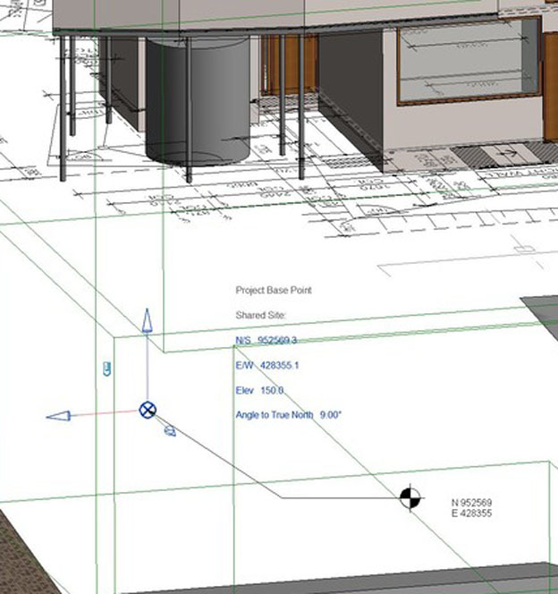
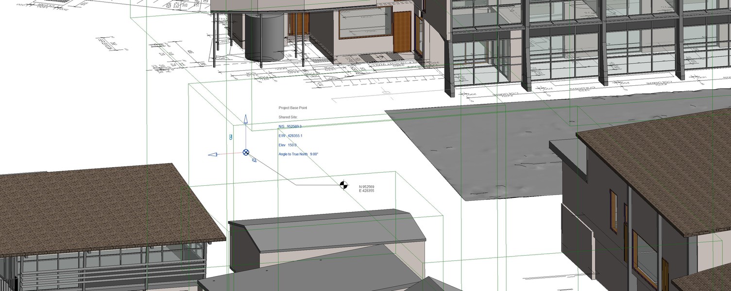
So back to what to use – again personal preference – use a coordinate system that is based on MGA – but truncated coordinates and well documented – and documented, especially importantly against physical reference marks – that is – don't make your project base point the corner of the lot, or the corner of the building or some random point out in the middle of the river – from a survey perspective – we want the project base point somewhere we can set a tripod over and have it already marked with a screw or even better a permanent survey mark – with plenty of other marks around to reinstate ,in case this one gets knocked out.
Also, best to avoid negative coordinates – so your project base point should be south-west of your site.
Personal preference here, but this site file should be locked up at this point. Your project or building specific data should be linked to this file, so any rotations are limited to the project. This way, if you insert point cloud or other survey data, it is as per the original local system.
Now you have your X,Y base point sorted – for your angle to true north you could use the side of a building – but again, get your surveyor to set this. No building is perfectly square and straight. Sit down with your surveyor and discuss your preferred option, then the surveyor can set this angle for you, even whack in a couple more reference datum points that then lead into your project grid design. The angle is then set with a highly accurate total station and well documented as part of the project control plan.
How accurate are these total stations? Typical instruments measure angles to 5 or 3 seconds-of-arc – even 1-second of arc is common now – so one minute of arc is roughly the width of a 20c piece at 100m – the 1-second instrument can "split" that horizontally into 60 slices .. from 100m away.
Again, do all of this at the beginning of the project! Spend a few dollars on setting this right. Don’t just get a PDF from somewhere and start digitising. PDF's are approximate and have their own coordinate system (the page). Why are PDF's approximate? PDF's are a graphics file only – the page is printed at 600 dots-to-the-inch (say – could be 300/1200). Coordinates are at best therefore at 600dpi as well and depending on the scale of the document, your real-world coordinates could be very course and very "rounded off".
So maybe spend a few dollars and get a "Revit Coordination Survey" done!
What do I export?
Surveyors will want any exported data back on the local/shared coordinate system – we want our original coordinates back to seamlessly drop data in/out of our work. All reference control marks should also be transferred to double check the transformations.
Machine guidance types will want MGA – but make them responsible for the transformation, scaling and epoch – but your "Project Control Plan" or similar will have all the necessary data for this.
In the end this is probably a Holden-Ford style argument – at least for people who are used to working with geodetic data.
This is more about preventing errors because people don't necessarily know what they are asking for – no doubt they have cut-and-paste "data on MGA" from tenders from years back without ever wondering why.
The Future
It isn't long now until all trades can do automated set out from the mode, give it 3 years. As it stands you can buy relatively cheap total stations that have set out apps that run on tablets that uses the model/IFC.
Your plumbers, HVAC guys etc will all have access to these types of set out tools.
What will your surveyors set out?? Control points, grids – the stuff that warrants higher order precision. You won't need us to set out every wall, every hanger.
But we will need the model and the control points to agree! That is the model will ideally be on a local coordinate system with well defined local control points around the construction site.
We will also be doing the model validation – expect us to rock up with high speed laser scanners and check what is being built agrees with the model. Expect us to be flying drones and producing high definition orthophotos that drop straight in to your floor plans.
Let your surveyor get the coordinates part of your BIM execution plan sorted
BEFORE you get too far into your models and all of this will work,
at least a heap better than it currently seems to!
And since you made it this far, one final tidbit ..